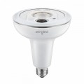
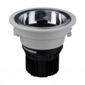
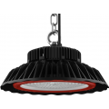
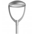
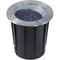
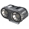
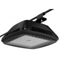
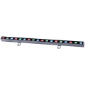
An LED dimmer is the term for a device that performs a dimming control operation within such an LED lighting device. LEDs react instantaneously to alterations in power input, making solid state lighting especially suitable for dimming scenarios. Dimming operation is engineered to change luminance or brightness of an LED luminaire in accordance with external disturbance applied thereto. An LED dimmer is provided to an LED luminaire with the intention to cut down energy consumption of the LED in the LED luminaire while securing efficient operation thereof. As a way to control luminance of such a lighting device, a number of dimmers are being used. Furthermore, to receive user input for controlling luminance of the luminaire, various dimmer switches are employed.
There are various varieties of dimming technologies for lighting applications. In offline LED dimming application, there are two forms of most popular dimmers available in the market. The first is forward-phase dimmer (Triac dimmer); and the second is reverse-phase dimmer (Transistor dimmer). A Triac (Triode for Alternating Current) is a bidirectional thyristor device for alternating current which may be regarded as a switch that is able to conduct current in either direction. A Triac circuit operates by delaying the beginning of each half-cycle of alternating current (ac) power, which is referred to as "phase control." By making use of the Triac phase-controlled operating principle, the supply voltage of the lamp circuit is regulated by controlling the conduction angle of the Triac element to chop out a part of the sine wave voltage input from the AC power network, to reduce the average value of the output voltage, as a way to realize the dimming function for LEDs. This is what's called phase dimming since it is often convenient to specify the position of the missing voltage with regards to a fraction of the period of the AC input voltage measured in degrees. A forward-phase triac dimmer cuts out a portion of the AC waveform at the leading edge of each half sine wave. On the contrary, a reverse-phase dimmer cuts out a portion of the AC waveform at the trailing edge in order that the dimmer turns off part-way through the sine wave. For forward-phase Triac dimmer, there is minimum amount of holding up current and it is connected with the power level of the dimmer. The higher power is, the higher holding up current is in general.
Although Triac dimming has the positive aspects of uncomplicated control and simple installation, the voltage waveform of the power supply may be situated at a distortion status to give rise to the problems of a low PF and an elevated harmonic voltage. LED is a nonlinear element. Put simply, the ratio of voltage to current is not a direct proportional ratio. LED drivers provide a reactive load to the dimmer. Which indicate that the LED driver will distort the AC current and voltage drastically by drawing non-linear currents when operating. They also present a zero load condition to the dimmer each AC cycle. This sort of zero load condition leads to dimmer operation to misfire producing a "flicker" or perceived visual fluctuation in the intensity of illumination created. Except in cases where the regulated power supplies that drive the LED lamps are configured to recognize and react to the voltage signals from Triac dimming circuits in a desired way, the Triac dimming circuits will likely produce non-ideal results, which include limited dimming range, flickering, blinking, and/or color shifting in the LED lamps. For an LED luminaire to respond properly to a phase-control dimmer, it is important to include several functional blocks into the driver electronics. For instance, a sensor is frequently included for monitoring the AC input waveform before the power-factor-correction (PFC) stage and producing an output signal proportional to the volume of phase cut.
For AC line dimmers, there are two types of dimming control schemes: analog dimming and PWM (pulse width modulation) dimming methods. Analog dimming adjusts LED light output by directly modifying the DC current in the LED string, while PWM dimming realizes the same effect by changing the duty cycle of a constant current in the LED string to effectively modify the average current in the LED string. PWM is a process where a PWM control signal including a periodic sequence of pulses is employed to periodically interrupt current flowing throughout the LED string. By regulating the conduction or disconnection of the transistor by the PWM signal, the outputted driving voltage can be controlled to keep the LED current constant. For the reason thathuman eye can integrate or average the pulses of emitted light, the observed brightness of an LED illuminator that utilizes PWM dimming is generally proportional to the duty cycle of the pulsed LED current. PWM control may very well be realized with allocated controller integrated circuit (IC) chips or with some micro-controllers. In the majority of electronics converters with PWM control, the switching frequency is fixed.
The main downside of PWM dimming is a result of its very nature, and is associated with the fact that the LEDs are being turned swiftly on and off. Although PWM is a practical method of dimming, the high supply voltages that are required to power the LED strings could easily damage electrical components in the SSL system, especially those components which are connected in series with the LED string. This issue is particularly serious at low dimming levels in the event the LEDs are not conducting for large fractions of the PWM control periods. With a current source output, PWM dimming needs a shunt switch that shunts the LED current over the "off" pulses of the PWM cycle. Consequently, relatively high losses are realized in the main converter and the shunt switch for the reason that current to the LEDs is at a relatively high level. In an effort to keep the advantage of PWM dimming control scheme and make the LED driver superior reliability and the LED lamp extended lifetime, it is necessary that the frequency of PWM dimming control scheme is related with or the comparable tothe output frequency of dimmer; and the output PWM dimming pulse is covered by the output pulse from the dimmer further. Furthermore, the efficiency (Im/W) of LED's us relatively high at lower drive currents, and therefore known PWM dimming methods are less efficient than known analog dimming methods.
Analog dimming basically controls the drive current fed to the LEDs. Full brightness uses the full current. Analog dimming can control the brightness of an LED by adjusting the current value in the LED loop. The driver electronics linearly decreases the current to dim the LEDs. The main benefit of analog dimming is uncomplicated without any output noise; the negative aspect is that there is color shift as the LED driving current diminishes. Analog dimming can be easy to implement, but might not achieve the best overall performance. The efficiency of LEDs will probably increase at lower currents, but LEDs may not create a consistent color at lower drive currents. Analog dimming also has some disadvantages at low dim levels. For instance, if the LED current is lower than approximately 5% and as great as 30% of the full output rating, light levels might not be homogeneous between different LEDs, color shifts may appear, and at very low current levels efficiencies of the LED's tend to be relatively poor.


